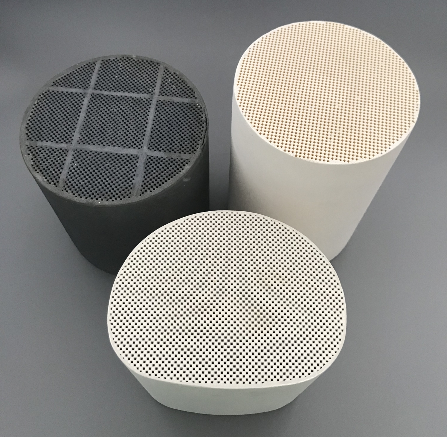
Soot accumulation follows engine duty, changing the filter’s pressure burden between regeneration events. An engine that spends long periods at low exhaust temperature may not clear soot in the same way as one that regularly reaches hotter operation. Flow, soot production, pressure allowance, and installation space also vary. Those conditions define the DPF problem before a ceramic material or shape is specified.
A catalyst manufacturer developing a dpf diesel engine solution must translate the engine’s pattern into a filter that captures particles without exceeding backpressure limits over its loading cycle. Geometry and material affect that balance, but a nominal CPSI figure cannot describe the whole installed result. The engine’s duty cycle sets the pressure and thermal problems that the proposed DPF must solve.
Start with the Engine Duty
Regeneration temperature can rise unevenly across a filter under high soot loading. Exhaust mass flow, temperature, soot output, engine speed and load, available package volume, and allowable pressure establish the filter’s task. Cold starts, idling, and sustained high load influence regeneration opportunities. A design that fits one engine family may behave differently on another with similar displacement.
The wall-flow principle remains constant across these versions. Exhaust crosses porous ceramic from inlet to outlet channels; particles remain within or on the walls. The accumulated layer can raise pressure and must be managed through regeneration. Engine-specific design changes how much surface and thermal margin is available; it does not remove the need to measure capture and loading behavior.
The dpf diesel engine duty also determines which conditions deserve the most test time. A short peak-flow run may reveal backpressure limits, while repeated low-temperature operation shows whether soot can accumulate faster than it is removed. A validation cycle should include the operating intervals that carry meaningful soot mass and thermal stress.
Choose Material and Geometry Together
A round or square body constrains filter-core space. Within that envelope, Hualian Catalyst‘s 100, 200, 300, and 350 CPSI options and custom dimensions alter channel density and flow area. Cordierite and SiC address differing thermal and mechanical demands. Emissions and loaded-pressure behavior emerge from the resulting assembly on the engine, including its loading and regeneration cycle.
SiC’s heat-conduction and strength characteristics can be useful where regeneration imposes demanding temperatures; Cordierite may suit a different cost or duty balance. The choice still depends on housing, canning, filter volume, and the control strategy. Material tests and assembled-unit tests answer different questions about survival and pressure behavior.
Changing face area alters gas velocity; changing length affects contact and pressure; changing cell density affects available channels and wall geometry. The parameters interact. A larger core can reduce flow restriction but may not fit the available space. A denser channel pattern can change capture and loading, yet an engine measurement is needed to determine whether the trade is useful.
The term catalyst manufacturer can be misleading when applied to a DPF, because soot capture is a wall-flow filtration task even if catalytic functions are also present elsewhere in the exhaust system.
The proposal needs a precise device description: material, channel arrangement, outer dimensions, canning, and the regeneration method. That description prevents a DOC or SCR specification from being mistaken for the filter requirement.
Validate Capture across Regeneration States
Choosing an intervention point for accumulated soot sets a thermal design case: active heating may be necessary when engine exhaust cannot sustain passive oxidation. A control plan must identify the loaded state that triggers intervention and the temperatures the filter can tolerate. Repeated events create a different endurance demand from a single clean-filter pressure reading.
Tests should therefore report particulate capture, pressure drop at defined flows and soot loads, regeneration response, and condition after thermal exposure. A dpf diesel engine result is meaningful only when the specimen matches the proposed material and geometry. A laboratory core and a production canister may not have the same flow distribution or mechanical constraints.
Single-speed testing cannot describe filter loading. Pressure readings at matched flow before and after soot deposition show the changing burden; regeneration tests then reveal whether usable flow returns without cracking or excessive thermal exposure. Those records tie geometry to the specific engine duty.
Requirement analysis and system optimization begin Hualian’s OEM/ODM route with operating measurements. Product design converts them into a drawing; manufacturing, testing, and delivery follow. The DPF test plan lets the engine maker compare customized construction against engine duty before accepting the configuration.
Design revisions need their own record. If packaging changes diameter, length, or inlet routing, prior pressure or regeneration data may no longer apply. A catalyst manufacturer can use the OEM/ODM process to link each drawing revision with its measured result and delivery specification. The relationship makes the customization auditable rather than a list of available options.
The final DPF design is an engine-specific agreement among capture, pressure, thermal behavior, and packaging. Requirement analysis identifies the duty, selectable material and geometry shape the candidate, and testing decides whether the assembly survives its loading and regeneration cycle. Regeneration strategy constrains cell density, material, and packaging alongside the actual engine’s exhaust-flow demands.
